
Skip to content

What Is HDD Drilling and How Does It Work?

Horizontal Directional Drilling (HDD) is a trenchless construction method for installing underground utilities with limited surface disruption. It can place water lines, fiber-optic cables, gas pipelines, and electrical conduits beneath roads, rivers, and landscaped areas. The process usually includes a pilot bore, controlled reaming, and product-pipe installation. Drill Hdd equipment guides a drill head through the soil while operators monitor depth, direction, and ground conditions.

A typical project begins with engineering surveys and utility locating. Soil reports also matter, because clay, sand, rock, and groundwater can change drilling performance. The drill head sends a signal to a surface locator, helping the crew adjust the bore path in real time. Small corrections are often necessary. Ground conditions are rarely perfect.

After the pilot hole reaches its exit point, the crew enlarges the bore using reamers. Drilling fluid helps cool the tooling, carry soil cuttings, and stabilize the hole. The final pipe is then pulled through carefully. Experienced contractors check pullback force, bend radius, fluid pressure, and entry and exit angles. These details protect both the new pipe and nearby infrastructure.

HDD can reduce traffic closures, excavation waste, and restoration costs, but it is not suitable for every site. Poor planning, inaccurate utility records, or unexpected rock can create serious delays. Reliable results depend on competent design, qualified operators, site-specific calculations, and local approvals. A professional assessment should guide the method, rather than assuming HDD is always the fastest choice. That distinction matters.
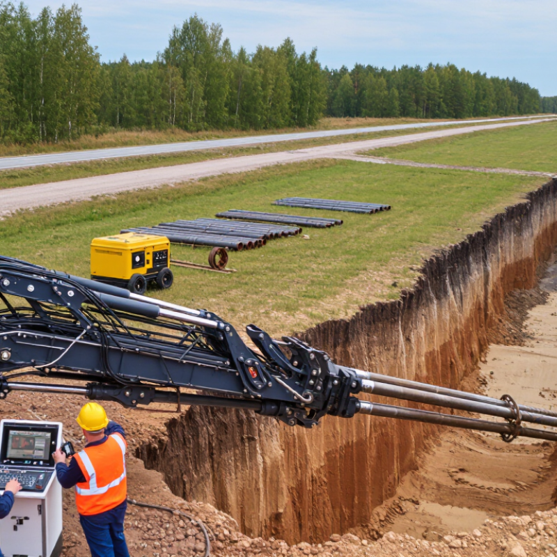
What Is HDD Drilling and How Does It Work?

What Is Horizontal Directional Drilling?

Horizontal Directional Drilling, or HDD, is a trenchless construction method for installing underground utilities. It is especially useful beneath roads, rivers, railways, and landscaped areas.

The process usually has three stages: pilot boring, hole enlargement, and product-pipe pullback. A steerable drill head follows a planned underground path. An operator tracks its position using electronic locating equipment. Drilling fluid cools the cutting tool and carries soil back to the entry pit. Reamers then enlarge the pilot hole. Finally, the pipe is pulled through carefully. Small changes in soil can affect the line.

The U.S. Federal Highway Administration identifies HDD as a method that can reduce traffic disruption and surface restoration compared with open-cut work. A North American Society for Trenchless Technology technical guide also stresses accurate utility locating, bore planning, and drilling-fluid control. These reports support HDD’s value, but results depend on ground conditions and crew experience. It is powerful, not flawless. A design may look sound and still fail in unexpected cobbles.

Tips: Review geotechnical data before selecting equipment. Confirm existing utilities with records and field locating. Keep entry and exit pits stable. Monitor drilling pressure, fluid returns, and bore alignment continuously. If returns disappear, stop and investigate. Rushing here creates expensive problems.

Key Equipment and Materials Used in HDD Drilling

Horizontal directional drilling uses a surface-launched drill string to create underground paths with limited excavation. A pilot bore begins with a steerable drill head, fitted with cutting jets or replaceable cutters. A downhole transmitter sends location data to a surface locator. The locator tracks depth, pitch, and direction. This information guides steering corrections. Signal interference or dense ground can reduce accuracy, however.

Drill rods transfer rotation, thrust, and drilling fluid through the bore. Their connections must resist bending and repeated loading. A mixing system prepares fluid, commonly using water, bentonite, and selected polymers. The fluid cools the cutting head, carries soil outward, and helps support the bore walls. Pumps must provide steady pressure. Mud recycling equipment can separate solids and reduce waste.

After the pilot hole reaches its exit point, a reamer enlarges the bore. Its size depends on the product pipe, soil conditions, and required clearance. A swivel connects the reamer to the pipe during pullback and helps reduce twisting. Conduit may be made from high-density polyethylene or another approved material. Pullback heads must grip the pipe without damaging its surface. Field teams often adjust fluid properties after observing returns. Mud recipes are not always perfect on the first attempt. Soil changes can expose that weakness quickly.

What Is HDD Drilling and How Does It Work? - Key Equipment and Materials Used in HDD Drilling
Category Equipment or Material Main Function Typical Technical Details Key Considerations
Drilling Process Horizontal Directional Drilling (HDD) A trenchless installation method used to place pipelines, conduits, and cables beneath roads, rivers, railways, and other obstacles. The work is normally completed in three stages: pilot bore, hole enlargement, and product pullback. Ground conditions, installation length, required depth, and product size must be evaluated before drilling.
Planning and Survey Site Survey and Utility Locating Equipment Identifies existing underground utilities, surface restrictions, access points, and the proposed bore path. May include electromagnetic locating tools, ground-penetrating radar, survey instruments, and utility records. Accurate utility information helps reduce strike risk and supports safe bore-path design.
Primary Equipment HDD Drilling Rig Provides thrust, rotation, and controlled movement to advance the drill string through the ground. Rig capacity is commonly evaluated by pullback force, rotary torque, drilling-fluid flow, and bore length capability. The rig should be matched to soil conditions, bore diameter, installation length, and product pullback load.
Bore Creation Drill Rods Transfer rotational force, thrust, and drilling fluid from the rig to the downhole tooling. Rods are connected in sections and must provide sufficient strength, flexibility, and threaded-joint reliability. Rod selection depends on bore length, curvature, torque, and the required drilling-fluid pressure.
Pilot Bore Pilot Drill Head Creates the initial small-diameter bore and allows the operator to steer the drilling path. Steering is achieved by changing the drill head orientation and controlling thrust and rotation. The pilot bore establishes the final alignment, grade, entry point, and exit point.
Navigation Downhole Sonde and Locating System Transmits information about the drill head position, depth, pitch, and direction to the surface operator. Common systems use a transmitter located behind or near the drill head and a handheld or walkover receiver. Signal quality can be affected by depth, soil composition, electromagnetic interference, and metallic objects.
Bore Enlargement Reamer or Hole Opener Enlarges the pilot bore to a diameter suitable for the product being installed. Reamers are selected according to soil type, required bore diameter, cutting action, and drilling-fluid circulation. The final bore is often made larger than the product diameter to provide clearance and reduce pullback resistance.
Drilling Fluid System Drilling-Fluid Mixing and Recycling Unit Mixes, supplies, separates, and recirculates drilling fluid during the operation. The system may include a mixing tank, pumps, hoses, screens, hydrocyclones, and solids-control equipment. Fluid management helps control viscosity, remove drilled solids, and limit waste generation.
Drilling Material Bentonite-Based Drilling Fluid Stabilizes the borehole, transports cuttings, cools tooling, and reduces friction between the product and surrounding soil. Bentonite is a clay material that forms a gel-like suspension when mixed with water. Fluid properties should be adjusted for soil conditions and monitored to prevent excessive pressure or inadvertent returns.
Drilling Material Water Acts as the carrier liquid for bentonite and other approved drilling-fluid additives. Water quality and supply volume influence mixing performance and fluid consistency. Local environmental requirements may regulate water use, discharge, and disposal.
Soil Conditioning Drilling-Fluid Additives Modify fluid properties to improve lubrication, suspension, filtration control, or cuttings transport. Additives may be selected for reactive clay, sand, gravel, or other challenging ground conditions. Only suitable materials should be used, and handling must follow safety and environmental requirements.
Product Installation Pullback Swivel and Pulling Head Connects the reamer to the product and transfers pulling force while reducing torsional stress on the installed product. The swivel allows rotation of the tooling without transferring the same rotation to the pipe or conduit. Connections must be compatible with the product size, material, rated load, and planned pullback forces.
Installed Product Polyethylene Pipe Used for water, gas, wastewater, and other pressure or non-pressure pipeline applications. Its flexibility and fused joints make it suitable for curved underground alignments. Pipe wall thickness, allowable pulling force, bend radius, and temperature must be considered.
Installed Product Conduit or Duct Provides a protected pathway for electrical, telecommunications, control, or fiber-optic cables. Conduits may be installed individually or in multiple-duct configurations, depending on project requirements. Minimum bend radius, pulling tension, internal diameter, and cable installation requirements are important.
Support Equipment Drilling-Fluid Pump Delivers drilling fluid through the drill rods and downhole tooling at the required flow rate and pressure. Capacity is selected based on bore diameter, soil conditions, tooling design, and desired cutting transport. Excessive pressure can increase the risk of ground heave or inadvertent drilling-fluid returns.
Safety and Control Pressure, Torque, and Pullback Monitoring Tracks operating forces and fluid conditions to help control the drilling process. Important readings include thrust, torque, rotation speed, fluid pressure, flow rate, and pullback force. Unexpected changes may indicate hard ground, tooling problems, utility conflicts, or bore instability.
Completion Product Pullback Installs the prepared pipe, conduit, or cable duct by pulling it through the enlarged bore. Pullback is performed at a controlled speed while maintaining suitable lubrication and alignment. The product must be inspected for damage, and pullback loads should remain within the allowable limit.
Environmental Control Drilling-Fluid Containment and Disposal System Controls excess drilling fluid and separates or stores returns generated during drilling. Methods may include containment tanks, vacuum removal, solids separation, and approved disposal procedures. Work planning should address inadvertent returns, site cleanup, fluid reuse, and regulatory compliance.

How the HDD Drilling Process Works Step by Step

What Is HDD Drilling and How Does It Work?

Horizontal directional drilling, or HDD, installs underground utilities with limited surface excavation. The process starts with route planning, permit checks, soil review, and utility locating. Ground-penetrating surveys help, but they are not perfect.

The Common Ground Alliance’s 2023 DIRT Report recorded more than 200,000 documented excavation damages in the United States and Canada. That figure shows why field verification remains essential before drilling.

The crew then positions the drill rig at the entry point. A steerable pilot bore follows the planned underground path. An operator adjusts the drill head using its transmitter, pitch, depth, and clock-face orientation. Drilling fluid cools the tooling and carries cuttings toward the entry pit.

Soil conditions can change quickly. A route that looks simple on a drawing may become difficult in gravel, clay, or fractured rock.

After the pilot bore reaches the exit point, reamers enlarge the opening in controlled stages. The final conduit is attached behind a swivel, then pulled through the prepared bore. Pullback speed and fluid pressure require constant monitoring.

Excessive force can damage the conduit or disturb nearby ground. The 2022 HDD Good Practices Guidelines from the North American Society for Trenchless Technology emphasize planning, drilling-fluid control, and documented observation.

Crews typically verify depth, alignment, conduit condition, and surface restoration after installation. Some decisions still depend on experience. Bore logs may reveal assumptions that need correction.

Common Applications of Horizontal Directional Drilling

What Is HDD Drilling and How Does It Work?

Common Applications of Horizontal Directional Drilling

Horizontal directional drilling (HDD) installs underground utilities with limited surface disruption. A pilot bore follows a planned path beneath roads, railways, rivers, or landscaped areas. A steerable drill head creates the first channel. The crew then enlarges it with reaming tools. Finally, a pipe or cable is pulled through the prepared bore. This method requires accurate locating, drilling fluid control, and clear communication. It is not a shortcut. Ground conditions can change unexpectedly.

HDD is commonly used for water mains, sewer lines, gas distribution, power conduits, and telecommunications cables. It connects buildings across busy streets without opening a long trench. Contractors also use it for river crossings, railway corridors, airport boundaries, and sensitive land. In residential areas, HDD can protect driveways, mature trees, and access routes. However, rock, unstable soil, shallow cover, or unknown services may increase risk. A site investigation should guide the method, not schedule pressure. Poor planning can cause settlement, fluid returns, or a failed bore.

Tips: Confirm utility records with field locating before drilling. Review soil data, entry and exit spaces, bore depth, and pulling force. Keep drilling fluid contained and documented. Use experienced crews and inspect the installed line. Small assumptions become expensive underground.

Advantages, Limitations, and Safety Considerations

Horizontal directional drilling (HDD) installs underground utilities with limited surface disturbance. A drill head creates a pilot bore beneath roads, rivers, or landscaped areas. The crew then enlarges the bore and pulls the product pipe through it. Guidance equipment tracks depth, direction, and drilling head position during the work.

Its main advantage is reduced excavation. Traffic, mature trees, pavement, and business access may remain mostly undisturbed. HDD can also shorten restoration time and reduce spoil removal. However, the method is not a perfect solution. Ground conditions matter greatly. Rock, unstable soil, unexpected voids, or groundwater can change the drilling plan. Drilling fluid may also escape through fractures and reach the surface. That event is called a frac-out.

Safety begins before the machine starts. Crews should review geological information, obtain required permits, and locate existing utilities using records and physical verification. Exposed utility points provide useful confirmation. A marked route is not enough. Operators need proper training, protective equipment, clear communication, and an exclusion zone around rotating equipment. Workers should monitor drilling pressure, fluid returns, and locator readings continuously. Emergency procedures must cover equipment movement, utility damage, fluid release, and loss of communication. In practice, production pressure can encourage rushed decisions. That risk deserves honest attention. A slower pause may prevent a serious incident.

What Is HDD Drilling and How Does It Work?

Horizontal Directional Drilling (HDD) is a trenchless construction method used to install underground pipes, conduits, and cables with limited surface excavation. The process generally includes pilot drilling, hole enlargement, and product pullback.

Typical HDD Installation Ranges

The chart shows indicative project ranges in metres. Actual performance depends on ground conditions, bore diameter, drilling fluid control, equipment capacity, alignment, and regulatory requirements.

  • Advantages: Less surface disruption, reduced traffic interference, fewer open excavations, and the ability to cross roads, railways, waterways, and landscaped areas.
  • Limitations: Difficult ground conditions, drilling-fluid loss, bore deviation, limited access for equipment, and the need for accurate underground utility information can increase project risk.
  • Safety considerations: Locate and verify existing utilities, establish exclusion zones, manage drilling-fluid pressure, control rotating equipment, use proper personal protective equipment, and monitor for inadvertent returns to the surface.